Cell board, pouch, multiple cells 1POxxxx, Cell Boards for multiple, stacked pouch cells - Notice: This product has been discontinued and is no longer available | |
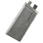
Each of these cell boards handles a number of pouch cells
(as opposed to a 1PO0000, which handles a single cell per board).
- Custom made to fit most sizes of large pouch cells
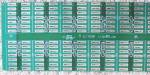
- Contains cell board electronics, connects cells together
- Placed horizontally, cell tabs are slipped into PCB, soldered to PCB
- One Cell Board per a group of cells in series (and, if required, in parallel as well)
- Compact: for cells as thin as 10 mm
- Narrow: for cells with spacing between tabs as little as 20 mm
- These cell boards require a BMS master to form a complete BMS
|
|
|
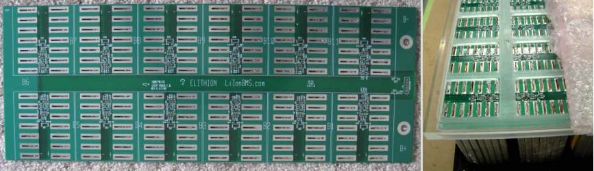
These cell boards can be used with a variety of pouch cells, in a variety of configurations.
|
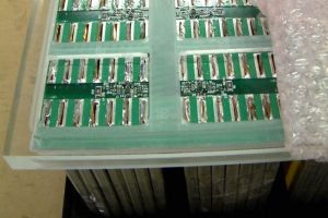 
Custom cell board for 12 cells in series, 7 in parallel, full bank
|
|
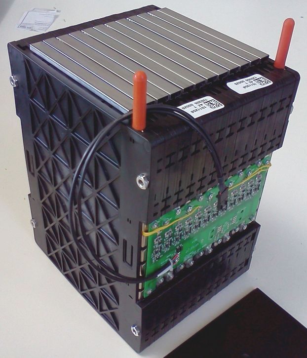
Installation is straightforward:
- Slip pouch cells in PCB and solder their tabs to the PCB
- If desired, also clamp the cell tabs together, to form a lower-resistance series connection
|
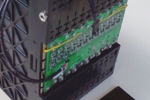
Cell board for Enerdel battery module: 12 cells in series, 2 in parallel, full bank
|
These standard Cell Boards are compatible with a wide range of pouch cells available on the market today, including:
- Amperex
- Compact Power / LG Chem
- EiG
- Electrovaya
- Kokam
- Optimum
- PHET
- Tenergy
General specifications (for detailed specifications, please see the Lithiumate™ Manual).
| Symbol
| Item
| Conditions
| Min
| Nom
| Max
| Units
|
| Vrange
| Cell voltage sensing range
| -
| 2.09
| -
| 4.54
| V
|
| Vaccur
| Cell voltage sensing accuracy
| Within Vrange
| -
| ±10
| ±15
| mV
|
| Isply
| Cell load current
| Stand-by
| -
| -
| 2.0
| µA
|
Active,
1-reading / sec
| -
| 1.5
| 2.0
| mA
|
| Balancing
| -
| 200
| -
| mA
|
| VISOL
| Isolation voltage
| End cell boards
Between battery & low voltage
| -
| 2500
| -
| V
|
| Item
| Dimensions
|
| Thickness w/components
| 0.071" / 1.79 mm
|
| Connector thickness, right angle
| 0.27" / 6.8 mm
|
A bank can be handled in one of two ways:
- Full bank: a single cell board handles the entire bank
- Split bank: 2 or more cell boards handle the bank:
- A positive cell board on its most positive cell
- A negative cell board on its most negative cell
- Zero or more mid-bank cell boards on any remaining cells
| Bank
| Type
| Range
| Cable to
BMS board
| Wires to adjacent cell boards
|
| Full
| Full-bank
| Handles the entire bank
| Through two 2-pin connectors
| N.A.
|
| Split
| Positive End
| Handles the post positive portion of the bank
| Red and black wires through a 2-pin connector
| A single wire to the next cell board
|
| Mid-bank
| Handles a central portion of the bank
| N.A.
| Two single wires, one to the previous cell board, one to the next one
|
| Negative End
| Handles the post negative portion of the bank
| White and green wires through a 2-pin connector
| A single wire to the previous cell board
|
Specifically:
- When a single cell board handles the entire bank, a "Full bank" cell board is used
- When 2 cell boards handle a bank, a "Positive end" cell board is used at the most positive end of the bank, and a "Negative end" one is used at the most negative end of the bank
- When 3 cell boards handle a bank, a "Positive end" cell board is used at the positive end, a "Mid bank" one is used in the middle, and a "Negative end" one is used at the negative end
- When n cell boards handle a bank, a "Positive end" cell board is used at the positive end, n-2 "Mid bank" ones are used in the middle, and a "Negative end" one is used at the negative end
Right angle connectors are standard on full bank and end boards.
Cell boards with straight connectors or no connectors are also available
Part number: 1PO1234B:
- 1 = Cell Board
- PO = Pouch
- 12 = Number of cells in series (available: 2 to 16)
- 34 = Assigned by Elithion for each custom board
- B = full bank (available: B = full bank; M = mid-bank; P = positive end; N = negative end)
These cell boards are made to order.
There is an additional NRE charge for these cell boards, for PCB layout and manufacture set-up.
To order, please see the Lithiumate BMS ordering form.