Vinci-LV Li-ion Battery Management System ESS BMS for large, low voltage batteries and arrays
Outstanding versatility, feature rich Li-ion Battery Management System
24 to 48 V Energy Storage Systems (ESS)
Li-ion or lead acid
Arrays of up to 100 batteries in parallel
Complete: just add cells
Off the shelf, stocked, as low as $ 350
A member of the Vinci BMS family .
Vinci LV battery master
Applications
>
Stationary
Solar installations
UPSs
Telecomm sites
Computer server farms
Pole mount
Mobile
House power
Marine
Auxiliary Power Units (APU) for trucks
Aviation
Job-site power
Portable devices
For applications other than low voltage batteries, see other Vinci BMS families
Specifications
Single battery:
24 to 48 V
Up to 16 Li-ion cells in series
Any chemistry
2 to 4 lead-acid batteries (12 V) in series
Positive or negative ground, or isolated
Energy (@ 100 %) or power (@ 50 %)
Up to 16 strings permanently in parallel*
Array of batteries:
Up to 63 batteries in parallel
Safe connection to bus (no inrush)
Managed as a single unit
Li-ion and lead acid hybrid on same bus
Requires N+1 modules for N batteries
Physical:
Centralized (1 case)
Rugged, sealed, industrial grade packaging
Sensing:
Wired (voltage tap wires to cells)
Distributed (cell moudules on cells)*
Bullet-proof against tap mis-connection
Hall Effect or shunt current sensing
Up to 5 thermistors
Balancing:
Top or mid, SoC based
Dissipative ("passive")
Charge transfer (active)
Protector switch:
Isolated MOSFET gate drivers
Drivers for contactors or latching relay
Internal precharge
20 A internal protector*
20 A to 1000 A external sensors and protectors*
Evaluation:
SoC (State of Charge)
Pack isolation
Data logging
Communications:
Isolated CAN communication link
USB port for troubleshooting
Field configurable through GUI
One of:*
XanBus™
ModBus RTU (RS485)
ModBus TCP-IP (Ethernet)
RS232
WiFi (Access point or station)
(*) Option
XanBus is a trademark of Schneider Electric.
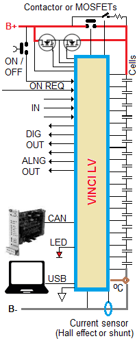
Block diagram
Examples
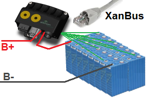
Single battery
16 LiFePo4 Li-ion prismatic cells in series: 48 V
20 A max current: protector switch inside BMS master
17 wires to the 16 cells to sense voltage
Fitted with optional XanBus™ interface for Scheider Electric invereter
48 V battery with XanBus™
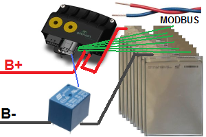
Single battery
7 NMC Li-ion prismatic cells in series: 24 V
50 A max current: current sensor inside BMS master, external contactor
Fitted with optional RS485 interface for MODBUS RTU
24 V battery with MODBUS
Single battery with 2 strings permanently connected in parallel
7 NMC Li-ion prismatic cells in series in each string: 24 V
20 A max current: protector switch inside BMS master
Each slave handles one string, with 8 wires to the 7 cells to sense voltage
Battery with parallel strings
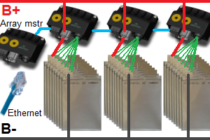
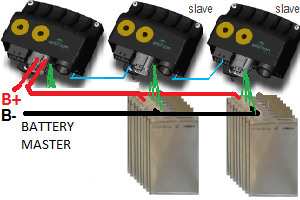
Array of 3 batteries
Array managed by an Array Master
Array Master fitted with optional RS485 interface for MODBUS RTU
Each battery managed by a Battery Master
Each string consists of 14 NMC Li-ion prismatic cells in series: 48 V
For each battery, 15 wires to the 14 cells to sense voltage
Battery array
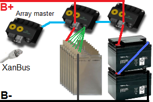
Array of mixed batteries
Array managed by an Array Master
Array Master fitted with optional XanBus™ interface for Scheider Electric invereter
Each battery managed by a Battery Master
First string consists of 7 NMC Li-ion prismatic cells in series: 24 V
For first battery, 8 wires to the 7 cells to sense voltage
Second string consists of two 12 V lead acid batteries in series: 24 V
For second battery, 3 wires to the 2 batteries to sense voltage
Mixed battery array
XanBus is a trademark of Schneider Electric.
Design & order your BMS
To design a BMS for your high voltage stationary battery, start by selecting one of these 2 topologies or contact us for help :
Wired, Centralized: A wire to each cell, one single module
Distributed, VinciBus: A module on each cell, fiber-optic to the Master
Wired, VinciLink: A wire to each cell, 2-wires between adjacent slaves; for strings permanently in parallel
Centralized topology
A single module performs all the BMS functions;
it senses cell voltages through a number of tap wires.
The BMS consists of:
A Centralized Battery Master
Up to 2 current sensors
A power switch (contactors or MOSFETs)
Optionally, to manage an array of batteries as a single unit, an Array Master
Detailed technical Info
Centralized topology
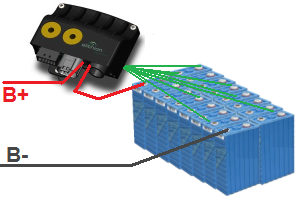
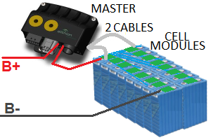
Distributed topology
A single Battery Master module performs most BMS functions.
A cell module is mounted on each prismatic cell to measure and report voltage and temperature.
The Battery Master is connected to the 2 cell module at the end of the battery through 2 small cables.
The BMS consists of:
A Centralized Battery Master
One cell module per cell
Up to 2 current sensors
A power switch (contactors or MOSFETs)
To manage an array of batteries as a single unit, an Array Master
Detailed technical Info
VinciLink topology
This topology is for batteries that have strings connected directly and permanently in parallel.
(If not, each string forms a separate battery, each requiring its own BMS.)
The BMS uses a Master/Slave topology, consisting of a Master and a number of modules;
communication between them is through a 2-wire daisy chain.
The Slaves sense cell voltages through a number of tap wires.
The BMS consists of:
A Battery Master
A number of VinciLink Slaves
Up to 2 current sensors
A power switch (contactors or MOSFETs)
To manage an array of batteries as a single unit, an Array Master
Detailed technical Info
VinciLink topology for strings in parallel
Which one?