|
|
Cell board, small cylindrical, multiple cells 1SCxxxx, Cell Boards for multiple, side-by-side 18650 and 26650 cells - Notice: This product has been discontinued and is no longer available | |
Each of these cell boards handles a number of small cylindrical cells in series, mounted side-by-side, in which cells in series are oriented in alternating polarity
(as opposed to a 1SC0100, which handles a single cell).
- Matched to industry standard 18650 and 26650 sizes
- Mounted on the side of the cells, by their welding tabs
- One Cell Board per a number of cells (or sets of multiple cells in parallel)
- Simplifies installation and improves reliability (though at the cost of loss of flexibility, compared to single-cell cell boards)
- Very thin, components are placed in space between cells: as little as 0.05" is added to battery dimensions
- A single communication wire is used between adjacent cells in a bank
- These cell boards are done to order and require a BMS master to form a complete BMS
|
|
|
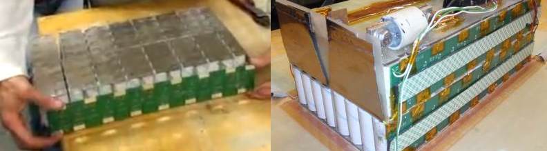
Multiple cell boards are installed onto the cells easily.
Installation is straightforward:
- Place cell board on the cells
- Fold the tabs from the cells down onto the cell board
- Solder the tabs
|
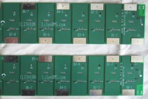 
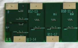
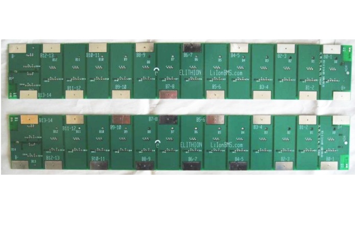
Cell board for 15 cells in series;
straight (top) and mirror (bottom)
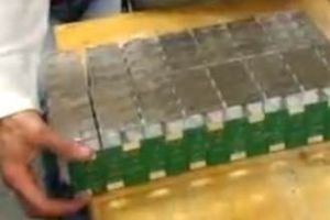
Installing the cell board on a pack.
|
These standard Cell Boards are compatible with a wide range of Li-Ion small cylindrical cells available on the market today, including:
| Brand
| Model
|
| A123
| M1 26650
|
| Advanced Battery Factory
| 18650 and 26650
|
| Aleees
| HIBS 18650E - 18650, energy, 2.7 Ah; HIBS 18650P - 18650, power, 2.4 Ah; HIBS 26650E - 26650, energy, 2.7 Ah; HIBS 26650P - 26650, power, 2.4 Ah
|
| Baoding Fengfan New Energy Co
| IFR18650D30 - 18650, 1.3 Ah; IFR26650D10 - 26650, 3 Ah; IFR26650D20 - 26650, 2.4 Ah
|
| CENS Energy-Tech
| 18650P - 18650, power, 1.1 Ah; 26650P - 26650, power, 2.5 Ah; 26650E - 26650, energy, 3.2 Ah
|
| Huanyu
| 18650
|
| K2 Energy
| LFP18650P - 18650 Power 1.2 Ah; LFP26650P - 26650 Power 2.5 Ah; LFP26650EV - 26650 Energy 3.2 Ah
|
| PHET / Pihsiang Energy Technology
| 18650 - 1.1 Ah
|
| PSI
| 26650
|
| Valence
| IFR18650E - 18650, 1.3 Ah; IFR26650 - 26650, 2.4 Ah
|
General specifications (for detailed specifications, please see the Lithiumate™ Manual).
| Symbol
| Item
| Conditions
| Min
| Nom
| Max
| Units
|
| Vrange
| Cell voltage sensing range
| -
| 2.09
| -
| 4.54
| V
|
| Vaccur
| Cell voltage sensing accuracy
| Within Vrange
| -
| +/-10
| +/-15
| mV
|
| Isply
| Cell load current
| Stand-by
| -
| -
| 2.0
| µA
|
Active,
1-reading / sec
| -
| 1.5
| 2.0
| mA
|
| Balancing
| -
| 200
| -
| mA
|
| VISOL
| Isolation voltage
| Low voltage to battery
End cell boards
| -
| 2500
| -
| V
|
| Item
| Dimensions
|
| Pitch
| 13, 22.5, 26, 45 or 52 mm
|
| PCB width
| Number of cells * pitch + 0.75" / 19 mm
|
| PCB Length
| 2.5" / 63.5 mm
|
| Thickness w/components, mid-bank board
| 0.071" / 1.79 mm
|
| Connector height, right angle, end board
| 0.27" / 6.8 mm
|
A bank can be handled in one of two ways:
- Full bank: a single cell board handles the entire bank
- Split bank: 2 or more cell boards handle the bank:
- A positive cell board on its most positive cell
- A negative cell board on its most negative cell
- Zero or more mid-bank cell boards on any remaining cells
| Bank
| Type
| Range
| Cable to
BMS board
| Wires to adjacent cell boards
|
| Full
| Full-bank
| Handles the entire bank
| Through two 2-pin connectors
| N.A.
|
| Split
| Positive End
| Handles the post positive portion of the bank
| Red and black wires through a 2-pin connector
| A single wire to the next cell board
|
| Mid-bank
| Handles a central portion of the bank
| N.A.
| Two single wires, one to the previous cell board, one to the next one
|
| Negative End
| Handles the post negative portion of the bank
| White and green wires through a 2-pin connector
| A single wire to the previous cell board
|
Specifically:
- When a single cell board handles the entire bank, a "Full bank" cell board is used
- When 2 cell boards handle a bank, a "Positive end" cell board is used at the most positive end of the bank, and a "Negative end" one is used at the most negative end of the bank
- When 3 cell boards handle a bank, a "Positive end" cell board is used at the positive end, a "Mid bank" one is used in the middle, and a "Negative end" one is used at the negative end
- When n cell boards handle a bank, a "Positive end" cell board is used at the positive end, n-2 "Mid bank" ones are used in the middle, and a "Negative end" one is used at the negative end
There are 4 possible orientations of the cells, based on which corner of the cell board is the '+' end.
To handle all 4 cases, these cell boards come in 2 versions ("straight" or "mirror"); by a 180° rotation, these two versions can handle all 4 cases.
The arrangement is slightly different between batteries with an even or odd number of cells in series.
|
Even number of cells
|
|
Odd number of cells
|
|
straight
'+' end at
top-left
corner:

|
mirror
'+' end at
top-right
corner:

|
straight
'+' end at
top-left
corner:

|
mirror
'+' end at
top-right
corner:

|

mirror
'+' end at
bottom-left
corner:
|

straight
'+' end at
bottom-right
corner:
|

mirror
'+' end at
bottom-left
corner:
|

straight
'+' end at
bottom-right
corner:
|
The pitch is:
- The spacing between alternating cell polarity
- Also the spacing between each set of cell contacts
- Also the the distance between adjacent circuits on the cell board
The pitch is determined by the arrangement of the cells:
- Matrix:
- Square
- Narrow hex (the front row of cells is all in one plane)
- Wide hex (the front row of cells is staggered)
- Number of cells in parallel along the front of the battery (typically 1 or 2)
- Cell diameter (e.g.: 18 mm for an 18650 cell, 26 mm for a 26650 cell)
| Pitch
| Square pattern
| Narrow hex pattern
| Wide hex pattern
|
| 13 mm
|
18650 cells, 8S8P:
1 row square
|
18650 cells, 8S8P:
1 row narrow hex
26650 cells, 4S4P:
1/2 row narrow hex
|
|
| 22.5 mm
|
|
|
18650 cells, 8S8P:
2 rows wide hex
26650 cells, 4S4P:
1 row wide hex
|
| 26 mm
|
18650 cells, 8S8P:
2 rows square
26650 cells, 4S4P:
1 row square
|
18650 cells, 8S8P:
2 rows narrow hex
26650 cells, 4S4P:
1 row narrow hex
|
|
| 45 mm
|
|
|
18650 cells, 8S8P:
4 rows wide hex
26650 cells, 4S4P:
2 rows wide hex
|
| 52 mm
|
18650 cells, 8S8P:
4 rows square
26650 cells, 4S4P:
2 rows square
|
18650 cells, 8S8P:
4 rows narrow hex
26650 cells, 4S4P:
2 rows narrow hex
|
|
Right angle connectors are standard on full bank and end boards.
Cell boards with straight connectors or no connectors are also available
Part number: 1SC0422B:
- 1 = Cell Board
- SC = Small Cylindrical, top-left corner is '+' end (available: SC = top-left corner is '+' end; SM = top-left corner is '-' end)
- 04 = 4 cells in a series (available: 2 to 16 cells)
- 22 = 22.5 mm pitch. Available: 13, 22.5, 26, 45, 52
- B = full bank (available: B = full bank; M = mid-bank; P = positive end; N = negative end)
These cell boards are made to order.
There is an additional NRE charge for these cell boards, for PCB layout and manufacture set-up.
To order, please see the Lithiumate BMS ordering form.
|
|