|
|
|
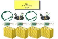
Lithiumate Lite Overview General description of the digital BMS for EVs | |
|
The BMS is powered:
- By the 12 V from the ignition, when the EV is on
- By the AC power whenever the EV is plugged into the wall
The BMS is connected to
- The traction pack
- The charger
- The motor controller
|
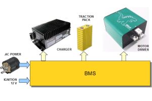

Overall block diagram
|
|
Measurement
- Measures and reports the cell voltages and temperatures in up to 8 banks of cells in a battery pack
- Measures and reports the battery pack current (bidirectional load current up to 900 A; charger current up to 30 A)
Evaluation
- Calculates and reports the State Of Charge of the battery pack
Management
- Balances the pack
- Dissipative (passive) balancing
- Top balance, voltage based
|
BMS in an application
|
|
Protection
- Turns off charger if any cell voltage exceeds a maximum, or the charging current is excessive
- Requests a reduction of motor drive if the battery is nearly empty
- Requests that motor controller be turned off if any cell voltage drops below a minimum, or the discharging current is excessive
- Disables charging and/or discharging if any cell's temperature is outside a range
- Disables charging and discharging if any cell board or bank stops reporting
- Prevents driving off when the vehicle is still plugged into the AC outlet
|
|
AC power connector
- AC Line input from the vehicle's AC plug (85 to 260 Vac)
- LED to indicate that AC power is present
Charger current sensor
- 30 Adc, charger DC output current sensor
No connector assembly required:
- AC power connector is 2-piece, screw clamp, terminal block
- Charger current sensor uses ring terminals mounted on screw terminals
|
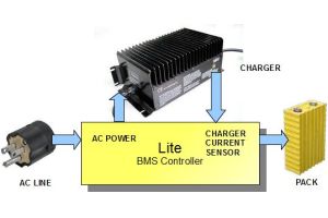
Charger interface
|
|
Ignition power input
- 12 V nominal, 50 mA nominal (no external loads)
- LED to indicate that Ignition power is present
Cable mounted current sensor
- Ready to plug-in
- Bidirectional, 900 A max
"Discharge OK" line, normally at 12 V, open when battery cannot deliver current
- Wire to the key input of the motor controller, or use to drive the main contactor
- Wire to a "Ready" lamp on dashboard
|
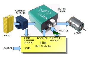
Vehicle traction interface
|
|
"Low Battery" line, normally at 12 V, open when battery charge is low
- Wire to the "Valet" input of the motor controller, to reduce available drive
- Wire to a relay to add resistance to the throttle, to reduce its range
- Wire to a "Reserve" lamp on dashboard
"Throttle Reduce" output, to reduce throttle range (2 or 3-wire pot, not HEPA)
- Insert in the "Wiper" line, between throttle and motor driver (for 3-wire throttle, a resistor must ve added)
- Wire to a relay to add resistance to the throttle, to reduce its range
- Isolated, for compatibility with motor drivers with pack referenced throttle
"Charge OK" line, normally at 12 V, open when battery cannot accept current
- Wire to the "Regen Enable" input of the motor controller, to disable regen
- Wire to brake pedal pot, to disable regen
"Fault" line, normally open, grounded when a fault is detected
- Wire to a "BMS fault" lamp on dashboard
- LED to indicate that there is a fault
No connector assembly required:
- Load current sensor comes with a connector
- Control connector is 2-piece, screw clamp, terminal block
|
|
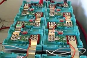
The BMS uses cell boards mounted directly on prismatic cells
- Up to 200 cells in series in a pack
- Divided into banks
- Each bank betweem 2 to 20 cells in series, recommended (users have used up to 25 cells)
- Cells directly in parallel count as one cell and use just inbe cell board
- Each bank has one positive end cell board, one negative end, and the rest are mid bank cell boards
- Each cell board measures its cell's voltage and temperature
- Posive end and negative end cell boards include an isolator, to isolate the high voltage of the pack from the 12 V supply
|
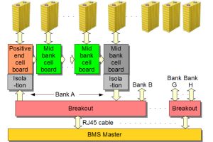
Block diagram of cell connections
|
|
Bank connectors
- Uses up to 4 each, RJ45 cables
- Each RJ45 cable connects the master to a breakout
- Each RJ45 cable and breakout handles 1 or 2 banks
- A breakout has 4 cables: two for positive end cell boards, 2 for negative end cell boards
No connector assembly required:
- Bank connections use off-the-shelf shielded RJ45 modular Ethernet cables (0.5 to 4 meters, as appropriate for the application)
- Complete modular cables are readily available from numerous sources
- Breakout at other end of modular cable is fully assembled
|
Traction pack interface
|
|
17 status LEDs on master
- "AC Power in": lit if powered by the AC line
- "Ignition power": lit if powered by the Ignition line
- "Charge OK": lit if charging is enabled
- "Discharge OK": lit if discharging is enabled
- "Warning": lit if the battery is nearly empty
- "Fault": lit if a fault was detected
- "Status": normally fully lit; in case of fault it flashes a code for the fault
- An LED for each bank indicates the satus of the communications for that bank
- Two LEDs by the USB connector flash when data is transmitted and received
|
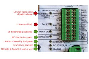
Status LEDs
|
|
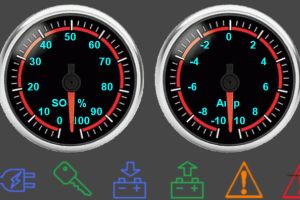
Three gauges on dashboard
- Drives standard fuel gauges (emulates fuel tank "sender")
- Configurable to match sender's characteristics (min and max resistance, direction)
- May be configured to drive a 5 V full scale meter
- Drives meters: battery current and voltage
- For 5 V full scale meters
- Full scale value configurable to match full scale on meter's face plate
- Designed to operate with popular Westach gauges
- Every controller LED function may be duplicated on dashboard with 12 V lamps
|
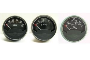
Ammeter, voltmeter, SOC meter
|
|
Graphics User Interface
- Computer based monitoring and configuration
- USB port for easy interface to the computer
- Uses a standard USB cable (no adapter dongle is required)
- Windows™ user interface
- Basic configuration takes only 4 steps
- One screen displays the complete status of the battery and the BMS
|
GUI application screen
|
|
AC power connector:
- AC power in, 85 to 265 Vac
USB connector:
- For connection to PC, during set-up and for troubleshooting
Current sensor connectors:
- Battery current sensor screw terminals, 30 A max
- Connector for prewired 900 A bidirectional load current sensor
|
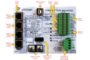
Front panel
|
|
Bank connectors:
- 4 connectors, each for 2 banks
- Each connector has 2 LEDs, one for ach bank, to indicate its status
- Uses standard shielded RJ45 modular cables
Control connector: (clockwise from top)
Two-piece terminal block, screw clamps
- Meter outputs:
- Pack voltage meter, configurable range, for 5 Vfs voltmeter
- Pack current meter, configurable range (may go negative), for 5 Vfs voltmeter (may be bidirectional)
- Pack SOC meter, emulates fuel gauge sender, configurable resistance, or for 5 Vfs voltmeter
- Power outputs:
- 12 V when powered by the AC line (0.3 A max)
- 12 V when powered either way (1 A max if powered from the Ignition line, 0.3 A max if powered by the AC line)
- 5 V when powered either way (50 mA max)
- Power input:
- 12 V from the Ignition line
- Control outputs:
- Charge OK: normally 12 V, open if charging is not allowed
- Discharge OK: normally 12 V, open if discharging is not allowed
- Fault: normally open, 12 V in case of fault
- OK: normally 12 V, open in case of fault
- Warning: normally open, 12 V at the end of battery charge
- Throttle: normally open, gradually lower resistance at the end of battery charge
|
|
|