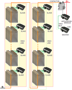
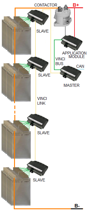
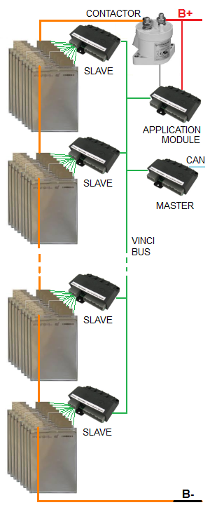
The traction pack is fully self contained.
A 12-cell slave is mounted by each group of 12 cells and wired to the cells.
A VinciLink goes from the master to the first slave; additional VinciLinks go from slave to slave.
A VinciBus goes from the master to the application module.
Components:
96 cells in series in 8 banks
Vinci-EV Battery Master, VinciLink
Vinci-EV application module
8 x VinciLink slaves, dissipative, 12-cell
Contactor set with precharge and current sensor
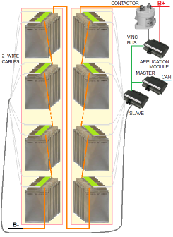
Split pack example: a 2-wire cable is run from the last slave in the first battery
to the first slave of the second batery.
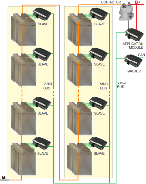
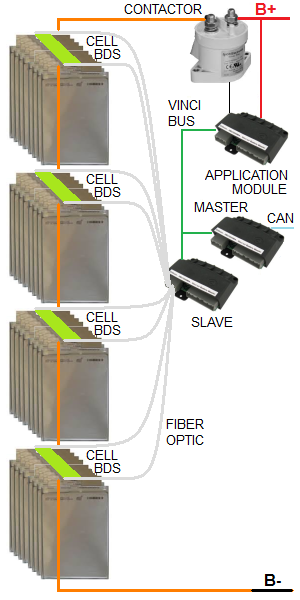
The traction pack is fully self contained.
A 12-cell slave is mounted by each group of 12 cells and wired to the cells.
A VinciBus goes from the master to the application module and to each slave.
Components:
96 cells in series in 8 banks
Vinci-EV Battery Master
Vinci-EV application module
8 x VinciBus slaves, dissipative, 12-cell
Contactor set with precharge and current sensor
Split pack example: the VinciBus is run from the Master (outside the batteries)
to the first battery, then to the second battery.
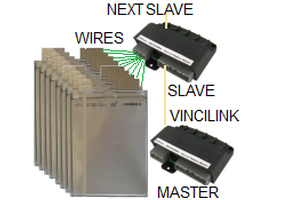
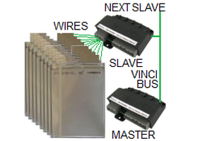
Slaves sense cell voltages through a number of tap wires.
The BMS uses a Master/Slave topology, consisting of a number of modules;
communication between slaves is through a 2-wire daisy chain;
between the Master and the Application module is through a 5-wire bus.
The BMS consists of:
A VinciLink Battery Master and an Application module
Wired: For N cells, N+1 voltage tap wires go from the slave to the cells.
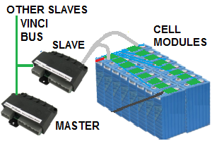
Distributed: Cells are divided into banks of up to 25 cells.
A cell module is mounted on each cell.
Two 2-wire cables go from the Slave to the two cell modules at the to ends of the bank.
Slave to Master
VinciLink
A Linear daisy chain (twisted pair) runs between the Master and the first VinciLink slave; one between each pair of adjacent VinciLink slaves.
VinciBus.
A parallel bus (5-wire) goes from the master, connects each module (slaves and application module), and ends in a terminator.
Pros & cons
Pros
Simple 1-wire / cell sensing
Simple 2-wire twisted pair link
Isolated slaves: safe, high noise immunity
Few electronic assemblies
Very high resolution measurement
Simple 1-wire / cell sensing
CAN based: Reliable, high noise immunity
Redundant string for fail-safe operation
Ideal for split packs
Few electronic assemblies
Very high resolution measurement
Spaghetti-free cell sensing
Integral temperature sensing
CAN based: Reliable, high noise immunity
Redundant string for fail-safe operation
Ideal for split packs
Cons
High voltage wire through battery
Requires additional thermistors, few measurement points
May not be suitable for use between boxes in a split pack
High voltage wire through battery
Requires additional thermistors, few measurement points