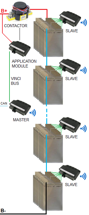
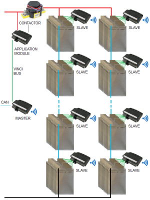
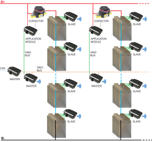
The BMS uses a Master/Slave topology;
the Battery Master communicates with its Slaves through a 5-wire VinciBus.
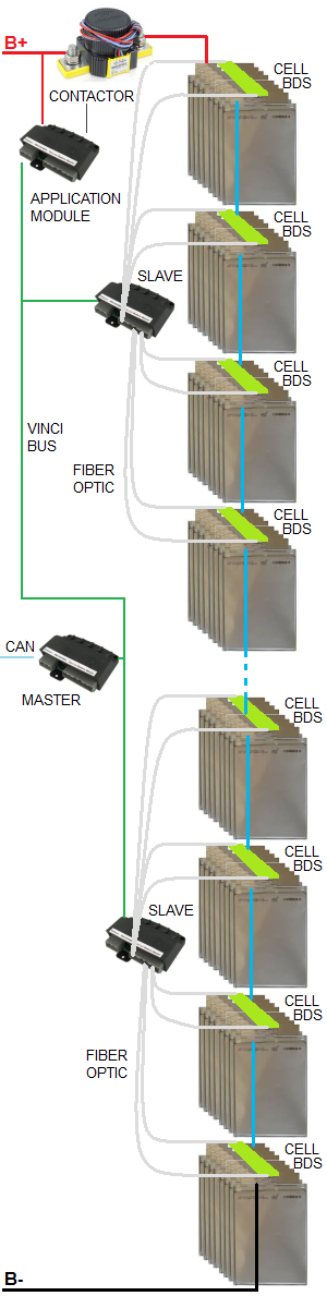
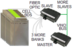
Cell sensing is distributed: a cell module is mounted on each cell to sense its voltage and temperature;
each slave manages a bank of up to 25 cells through 2 fiber optic cables.
Isolation is provided by the fiber optics.
The BMS consists of:
A VinciBus Battery Master and an Application module
A number of VinciBus Slaves
Up to 2 current sensors
A set of contactors
To manage an array of batteries as a single unit, an Array Master
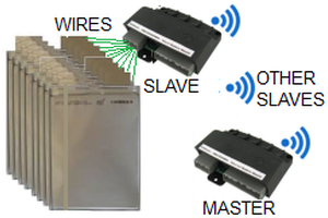
Wired: For N cells, N+1 voltage tap wires go from the slave to the cells.
Distributed: Cells are divided into banks of up to 25 cells.
A cell module is mounted on each cell.
Two optic fibers go from the Slave to the two cell modules at the to ends of the bank.
Slave to Master
VinciNet
Wireless communications between the Master and the slaves.
VinciBus.
A parallel bus (5-wire) goes from the master, connects each module (slaves and application module), and ends in a terminator.
HV isolation
Between the Master and the slaves, through a wireless link.
Between the cell modules and the slave, through fiber optics.