This page answers some of the most Frequently Asked Questions
⇪Can I replace Lead Acid with Li-ion in a solar installation?Yes. However, there are 2 things you need to be aware.
Please read this application note on Lead acid replacement. ⇪Is the high voltage side isolated from the low voltage side?Yes. There are optical isolators on the end cell boards that provide galvanic isolation. Therefore, the cell boards (up to the optical isolators) are connected to the high voltage side (the cells). Everything else is connected to the 12 V supply: the communication cables, the BMS controller, the CAN bus, the RS232 port the digital and analog inputs and outputs. 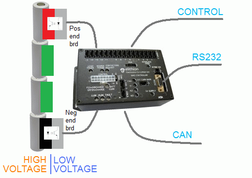
⇪Is there a fuse on the cell board?Recent cell boards (spring 2012) have a fuse. The fuse is not in series with the entire cell board circuit: it is only in series with the components that, if damaged, would slowly drain the cell to which the cell board is connected. What the fuse does:
What the fuse doesn't do:
All cell boards are safe: they do not cause fires, and they do not short across the cell.
The following boards have a fuse:
The following cell boards do not fave a fuse:
⇪Can I add fuses?Yes, but... Elithion discourages the addition of fuses to its BMS. Yes, fuses on the tap lines are a good idea in a non-distributed BMS. But the Lithiumate BMS is a distributed BMS, and, as such, is inherently a safer BMS in which electronics are only exposed to 3 volts or so, not the entire pack voltage. Therefore, no fuses are necessary. An in depth understanding of the full range of complex issues involved will reveal that added fuses:
Having said, that, if you absolutely must add fuses to a Lithiumate BMS, we would like to offer some guidelines There are four locations where someone may consider adding fuses:
NOTE: Elithion does not support customers who place fuses in series with a cell voltage sense wire.
Placing a fuse in series with a cell voltage sense wire will affect the voltage measurement, because of the voltage drop across the fuse during a measurement.
Placing a fuse in series with a communication wire between adjacent cell boards is OK and has no known side effects, other than loss of reliability and increased chance of unintended short circuits.
Placing a fuse in series with the communication harnesses from the BMS master to the positive end cell board is OK and has no known side effects.
Placing a fuse in series with the communication harnesses from the negative end cell board to the BMS master may result in loss of noise immunity, because the fuses are not shielded.
⇪Can I mount the cell boards off to the side?No. The Lithiumate is a distributed BMS: each cell board MUST be mounted directly on its cell. Do not attempt to use it as a centralized BMS: cell boards off to the side. 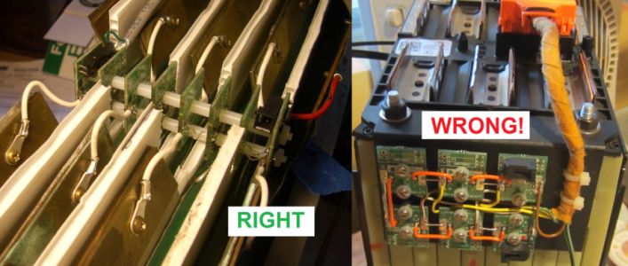
Right (cell boards directly on cells) and wrong way (cell boards off to the side) to use cell boards for pouch cells. Attempt to use it as a centralized BMS will result in improper operation: poor noise immunity, low accuracy, no temperature sensing. ⇪Where is the temperature sensor?In the cell board, marked "T1". For example, on a Pouch and on a Prismatic cell board: 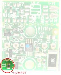
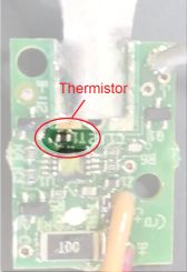
⇪Can I use external temperature sensors?No. Some have tried, with terrible results. The temperature sensors on the cell boards work quite well. While it is physically possible to remove the thermistor from the board and to replace it with leads going to a thermistor mounted on the cell, the functionality of the cell board will be severely compromised:
⇪Can I mount the Lithiumate on a pre-made battery module with a small BMS connector?No. In pre-made battery modules (such as those sold to model airplane hobbyists), there is no direct physical access to the individual cells. In a distributed BMS, the cell boards must be physically mounted directly on the cells. Therefore, a distributed BMS cannot be used on a pre-made battery module. A non-distributed BMS is required instead. Elithion does not make non-distributed BMS. You may not modify a Lithiumate BMS to work as a non-distributed BMS. It will misbehave and it will not protect the pack from operating outside its safe temperature range. ⇪Does the Elithion BMS log data?No. There is no data logging on the BMS. For that matter, there is no data logging in any controller used in vehicles. Yes, the BMS controller does log events (just a few events) as other vehicle controllers do, but not data. Data logging is a job best left to data loggers, which are product designed just for that purpose. Even if a BMS controller did data logging, its data (voltage, current and temperature) would be of limited use, without the ability to correlate it with what else was going on in the vehicle at the time. The best placement for a data logger, is on the CAN bus, where it is able to record a variety of information (e.g.: throttle position, RPM, battery status...). Just Google "OBD II logger" to get some possible solutions. ⇪Can I split the pack in 2 and use a charger on each half?Yes. With a high voltage pack, it is hard to find a charger that can handle the full pack voltage. You have two options:
In the latter case, you may want to split the pack in two, and have two chargers, one for each half of the pack. But then you are faced with the problem of how arrange the BMS. The Lithiumate BMS can only deal with one number for pack current (only one value for the SOC). Therefore: a) either you use 1 BMS, in which case the current must be exactly the same for both halves, b) or you must use 2 different BMSs. With a Lithiumate, you can use either of these two approaches, each of which has some limitations. The choice between 1 BMS and 2 BMSs depends on many factors:
Note that the isolation test function and the precharge resistor sense functions in the HVFE are limited to 800 V. With packs that can reach 800 V:
1 BMSIn this approach, one BMS looks at the entire pack as a single string, and controls both chargers at the same time. The Lithiumate can handle 255 cells, which is enough for high voltage packs. But, it can handle only one value for pack current, and it has only one output to turn a charger on and off. (Configure the BMS for a single series string, not for 2 batteries in parallel.) One slight problem is that the top half charger could be off because the BMS told it to, because a cell in the bottom half is too full, even though the top half of the battery could still accept charge. This is not really a problem, but the user may complain that one charger is off even though its half of the pack is still not full. A somewhat larger problem is that, with 2 chargers, the currents in the two halves of the battery are different. You can place the current sensor on one charger's output or on the other. The BMS will be able to estimate the SOC of whichever battery half has the current sensor. For the other half pack, the SOC will be off, in proportion to the difference between the output current of the two chargers. Even if the chargers were absolutely identical, they would behave differently once they go into the Constant Voltage mode, because of differences in the cells in their respective half of the battery. So, yes, it will work, but the SOC of one of the 2 halves (the one without the current sensor) will be off. CAN busThe problem does not go away if the chargers report the charger current through the CAN bus: the BMS can only handle one input message with pack current data. Another problem is raised if using the CAN bus: the value for the maximum pack voltage that the BMS reports to a CCCV charger. If the Constant Voltage point of the chargers is set independently of any data on the CAN bus, then there is no problem. But, if the Constant Voltage point of the chargers is set through the CAN bus, then the BMS must be configured as if the two halves of the battery were two strings in parallel (number of parallel batteries = 2); that way, the BMS calculates the correct CV point for the chargers: 1/2 the pack voltage. That solves the problem when charging, but then you may have a problem when the load is on, because the BMS reports only 1/2 the pack voltage. The solution involves adding some intelligence to a VCU (Vehicle Control Unit) or some such controller, to do one of two things:
As you can see, the first solution is much easier. 1 BMS and rectifiersHere is a clever circuit to split a pack: parallel charging, series discharging. 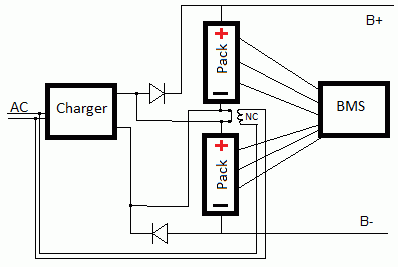
When the AC is available, the charger is on, and a contactor opens the series connection between the half packs.
When the AC is gone, the contactor closes, and the packs are connected in series.
To our knowledge, the Lithiumate BMS is the only BMS that can handle strings in parallel, and specifically the only BMS that can be switched on the fly between 1 series string and 2 strings in parallel. 2 BMSsIn this approach, 2 BMS are used, one for each half of the battery. Each BMS controls its own charger; therefore, the chargers are used more optimally. Also, each charger has its own current sensor; therefore, the SOC of each half is computed correctly. If each BMS controls its charger through the CAN bus, and there is no CAN bus to the load, then you can use two separate CAN buses, one for each charger. To control the load, the limit outputs of the 2 BMSs must be configured for normally open, and grounded if limited; that way the corresponding limit outputs of the 2 BMSs can be paralleled (LLIM to LLIM, HLIM to HLIM), and sent to the load. If a common CAN bus is used, then one of the BMSs must be configured so that the IDs of its messages do not conflict with the messages from the unmodified BMS; each charger must be configured to accept messages from its own BMS. If that common CAN bus is used to report to the system (say, a vehicle) the status of the battery, then a VCU (Vehicle Control Unit) is required; the VCU must be programmed to receive messages form both BMSs, each with its own set of IDs; the VCU must intelligently decide what the battery SOC is, given the SOC reported by each BMS. Note that you cannot use two HVFEs simultaneously to do an isolation test, as they will interfere with each other. ⇪Can I break the comm cable with a connector?Yes. The option of breaking the comm cables through a set of connectors is not something that we designed into the product. Therefore, we are not able to recommend a specific connector for the job. Should you decided to split the comm cable with a connector, do follow these guidelines:
⇪Can I use a different current sensor?Yes. While you are certainly free to use a different current sensor, other than the ones we sell, it is really your responsibility to assure that that sensor is compatible with your application and with the BMS controller.
⇪Can the BMS handle 2000 A?Yes, though with some limitations:
We offer workarounds, based on the application: 1) For applications that have continuous currents up to 600 A, and peaks up to 2000 A (e.g.: a race car):
2) For applications that have continuous currents of 2000 A.
For example, if the battery is 1000 Ah, and the current is 2000 A, configure the BMS for 250 Ah to report 500 A instead of 2000 A. That way, the SOC will be reported correctly. ⇪Are the boards conformally coated?Some.
The pouch and small cylindrical cell boards are soldered by the user; conformal coating would get in the way of soldering. The controllers include connectors that are not compatible with conformal coating: the coating would wick up onto the contact area and cause problems. In any case, our experience of systems that were inappropriately used in harsh environments is that the electronic boards have no problem, while the connectors can become badly oxidized. Conformal coating may give the user the false impression that these products may be used in harsh environments, when in reality, they cannot. The user must assure that the entire battery, including the BMS, be used in a protected environment. For marine applications, and other harsh environment applications, please contact us to discuss our sealed version of the product, available only in large volumes to industrial manufacturers. ⇪Can I use 1 BMS to manage 2 batteries?No. 1 BMS = 1 current sensor = 1 SOC value = 1 set of on-off control lines With two batteries, you have 2 currents, 2 SOC values, and each one needs to be turned on and off independently of the other. Therefore, 2 batteries = 2 BMSs. (To manage a small, 12 V, Li-ion battery, use a PCM - analog protector.) ⇪Can I use 1 BMS to manage more than 1 charger?In general, yes:
There are multiple problems when using multiple smart chargers, where no one charger is the master:
So, for smart chargers where no one charger is the master, you need a specialized controller that acts as the master. That way, the BMS only has to talk to one device, and listed to one device: that controller. To date, no charger manufacturer offers that product; specifically, Eltek told us that they do not intend to offer such product. Therefore, you will need to design your own solution (using a CAN bus gateway), or you can hire Elithion to design one for you. ⇪Does the BMS use CANopen?No. CANopen is a closed standard (ironically), and having a product certified is an expensive process. Also, CANopen adds a significant layer of complexity to the communications on the CAN bus, making it more busy than it needs to be. Therefore, Elithion products are not CANopen compatible, at least not directly. However, Gateways that convert a standard CAN bus communication to CANopen are readily available on the market. ⇪Does the BMS interface to motor drivers through the CAN bus?Some. From the point of view of control mothod, there are 3 types of motor drivers today.
The Lithiumate BMSs (Lite and Pro) are compatible with all motor drivers through simple wire control (# 1through 3 above) The Lithiumate Pro BMS is directly compatible with all motor drivers that include mesages that allow for direct interface to a BMS (# 3 above)
The Lithiumate Pro BMS is indirectly compatible with all motor drivers that do not include mesages that allow for direct interface to a BMS (# 2 above);
this is one through a central controller (usch as a VCU - Vehicle Control Unit).
This list of motor drivers shows which ones have CAN bus support, and, of those, which ones are directly compatible with a BMS in general, and therefore compatible with the Elithion Lithiumate Pro BMS.
|
Solar ▼
Isolation ▼
Cell board fuses ▼
Adding fuses to cell bd. ▼
Cell board off the cell ▼
Thermistor location ▼
Use ext. thermistors ▼
Use battery modules ▼
Logging ▼
Split pack 2 chargers ▼
Conn. on comm. cable ▼
Other current sensor ▼
Handle 2000 A ▼
Conformal coat ▼
One BMS 2 batteries ▼
Multiple chargers ▼
CANopen ▼
Motor driver through CAN ▼