App note: Lead Acid replacement with Li-ion Using a Lithiumate BMS | |
More and more people wish to replace their lead acid batteries with Li-ion batteries.
Batteries that consists of just Li-ion cells are not a direct, drop in replacement for lead acid batteries.
That is because they are somewhat different:
| Lead acid batteries
| Li-ion cells
|
| Managed by monitoring the battery pack voltage
| Managed by monitoring each individual cell voltage
|
| Survives being discharged down to 0 V
| Damaged if discharged below about 2 V / cell
|
| May be trickle charged
| Damaged if charged past 3.6 (or 4.2 V) / cell
|
| Benign if abused
| Risk of fire if abused
|
| Do not require a protection switch
| Require two protection switches: one for charging, one for discharging
|
| May be used at all temperatures
| Cannot be charged below 0°C, have a more limited temperature range
|
In addition to the Li-ion cells, a Li-ion battery used to replace a Lead Acid battery requires:
- A Battery Management System (BMS)
- A way for the BMS to stop charging when ANY cell is unable to accept any more current
- A way for the BMS to stop discharging when ANY cell is unable to deliver any more current
The problems with some systems that were originally designed for Lead Acid are that:
- They have no provision to control and stop charging current
- They have no provision to control and stop discharging current
- They use the same path for charging and discharging
Two separate paths are required because there are times when the battery is able to discharge, but not charge:
- Because a cell is full
- Because it's warm enough for discharging, but too cold for charging
Also, there are times when the battery is able to charge, but not discharge:
- Because a cell is empty
- Because the output is overloaded
The ideal solution is to change the system so that it does separate the charging and discharging path, and that each path may be controlled by the BMS.
However, that is not how present Lead Acid systems are wired.
Therefore, please let us propose this solution:
This example is for a 48 V battery, but the basic principle is applicable to other voltages as well.
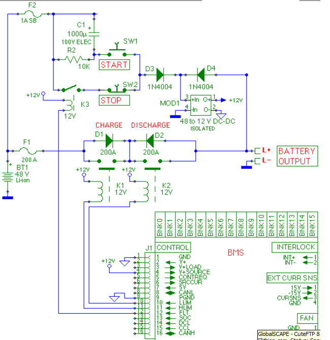
Suggested circuit for a Lead Acid replacement Li-ion battery using contactors
This circuit has the following advantages
- Operates just like a Lead Acid battery, in the sense that it has a single input/output port
- It controls charging and discharging separately, to protects the Li-ion cells from over charge and over-discharge
- It can be turned off (during transportation) and then woken up
- It prevents a user from forcing the battery on by holding down the Start button
- If works with charges that need to see the presence of a battery, even when the battery cannot discharge
Principles of operation:
- The BMS can control charging or discharging separately
- Normally, both contactors are on, and the battery is connected to the output
- If the BMS decides that the battery cannot charge, it opens the HLIM output, contactor K1 opens, and the battery can discharge through D1 and K2
- If the BMS decides that the battery cannot discharge, it opens the LLIM output, contactor K2 opens, and the battery can charge through D2 and K1
- If the BMS decides that the battery cannot charge or discharge, it opens both the LLIM and HLIM outputs, contactors K1 and K2 open, and the battery can neither charge nor discharge
- The BMS is powered by the cells or by a charger connected to the output of the battery
- Two diodes, D3 and D4, pick whichever voltage is higher
- A 48 V to 12 V DC-DC converter generates 12 V to power the BMS and the relays
- When the battery is connected to a load, the DC-DC converter is powered through relay K3 and diode D3
- When the battery is connected to a charger, the DC-DC converter is powered through diode D4
- At the end of charge, the BMS disable discharging into the load, but stays on, until it can't draw any more power from the cells safely
- If the cells are nearly empty, the BMS disables discharging by turning off contactor K2, but the BMS continues to be powered through relay K3
- If the cells are discharged even further, eventually the BMS issues a fault, which turns off relay K3; that in turn removes power to the BMS, and the battery is completely off
- To put the battery to sleep (such as during transportation to a new site), press the Stop button
- Pressing switch SW2 removes power to the DC-DC converter, shutting down the BMS (and therefore the battery); this also removes relay K3, so power is not restored when SW2 is released
- To wake-up the batery, connect it to a charger, or press the Start button
- Connect the battery to a charger; the charger's voltage powers the DC-DC converter through D4, and the BMS wakes up, turning on contactor K1; the charger can therefore charge the cells through rectifier D2 and contactor K1
- Alternatively, press the switch SW1; this applies a voltage pulse to the DC-DC converter input, enough to power it for just long enough so that the BMS wakes up, turns on the relay K3, and from then on powers itself from the cells, through relay K3 and diode D3
- Continuing to press SW1 has no effect, because the voltage pulse is of limited duration (due to capacitor C1); this prevents a user from forcing the battery on by holding down the Start button
- Once SW1 is released, capacitor C1 is slowly discharged through R2, after which its functionality is restored
Component selection:
- The DC-DC converter must be isolated, and must generate enough current for the contactor coils, plus 200 mA for the BMS and other loads
- The rectifier diodes D1 and D2, must be able to handle the continuous charging and discharging current, respectively
normally they are not expected to have to dissipate high power, because, typically, they only are used for a short time: D2 is only used until the battery is charged enough to allow discharging, and then K2 is turned on, bypassing D2; same for D1 and K1
use either two chassis mounted rectifier diodes, or just a single common cathode diode pair
- SW1 and SW2 could be a single center off momentary switch switch, normally closed on one side and normally open on the other side
- The value of capacitor C1 has to be higher than the capacitance on the input of the DC-DC converter
This other example uses Solid State Relays instead of contactors.
Unlike contactors, Solid State Relays use hardle any power in standby; on the other side, contactors can handle much higher current.
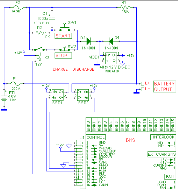
Suggested circuit for a Lead Acid replacement Li-ion battery using Solid State Relays