Vinci HV BMS, VinciBus topology Description, configuration and ordering | |
|
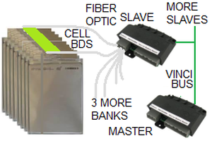
The BMS uses a Master/Slave topology;
the Battery Master communicates with its Slaves through a 5-wire VinciBus.
Cell sensing is distributed: a cell module is mounted on each cell to sense its voltage and temperature;
each slave manages a bank of up to 25 cells through 2 fiber optic cables.
Isolation is provided by the fiber optics.
The BMS consists of:
|
Item
|
Info
|
Function
|
Qty
|
| VinciBus Battery Master
| Info
| Manage the battery
| 1
|
| VinciBus Fiber-optic Slaves
| Info
| Interface to a bank of cell modules
| 1+
|
| Application module
| Info
| Add high voltage stationary battery functions
| 1
|
| Contactor set
| Info
| Precharge, disconnect the battery
| 1
|
| Current sensors
| Info
| Sense the battery current
| 0~2
|
| Prismatic cell modules
| Info
| Connection to prismatic cells
| 1/cell
|
| VinciBus wiring components
| Info
| Between master, appl. mod.
| 1
|
| Communications adapters
| Info
| To a computer for monitoring
| (1)
|
To manage an array of batteries as a single unit:
|
Item
|
Info
|
Function
|
Qty
|
| Array Master
| Info
| Manage the array
| 1
|
|
VinciBus topology
|
For spare parts, please contact us