Cell modules for prismatic cells Mechanically rugged, electrically protected | |
Each of these cell modules handles a single prismatic cell.
- Measures and reports voltage and temperature
- Matched to most sizes of prismatic cells
- Mounted on the top of the cell, through ring terminals
- Reliable mechanical mounting and direct electrical connection
- Inobstrusive: fits within the terminal bolts
- A single communication wire is used between adjacent cells in a bank
- For use as part of a Vinci or Lithiumate BMS
|
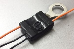
Primatic cell module
|
|
These cell modules can be used with most prismatic cells.
Single modules offer flexibility, as they can be used in a variety of cell arrangements.
These cell modules can be used with a variety of prismatic cells. They are available in various lengths, to accommodate various terminal spacings.
|
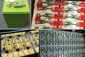

Vinci prismatic cell modules in applications
|
Each bank requires a positive cell board on its most positive cell, a negative cell board on its most negative cell, and mid-bank cell boards in the remaining cells.
(The quote form will automatically select the correct number and type of modules.)
Bolt
size
|
Part number
|
Positive
end
|
Mid
|
Negative
end
|
Standard
sizes
|
|
Cable
|
Optic
|
Cable
|
Optic
|
|
M4
|
3CP2sswP
|
3CP2sswH
|
3CP2sswM
|
3CP2sswN
|
3CP2sswL
|
-
|
|
M6
|
3CP3sswP
|
3CP3sswH
|
3CP3sswM
|
3CP3sswN
|
3CP3sswL
|
-
|
|
M8
|
3CP4sswP
|
3CP4sswH
|
3CP4sswM
|
3CP4sswN
|
3CP4sswL
|
3CP4117x: 110 mm, 2 W
3CP4188x: 170 mm, 5 W
|
|
M12
|
3CP6sswP
|
3CP6sswH
|
3CP6sswM
|
3CP6sswN
|
3CP6sswL
|
3CP6218x: 110 mm, 5 W
|
|
M14, M16
|
3CP8sswP
|
3CP8sswH
|
3CP8sswM
|
3CP8sswN
|
3CP8sswL
|
3CP8249x: 240 mm, 10W
|
ss = terminal spacing [cm]
w = balance power code: 6: 1 W; 7: 2 W; 8: 5 W; 9: 10 W
Example: Part number 1PR4117M
- 3 = Vinci
- PR = Prismatic cell module
- 4 = M8 bolt (bolt size = 2 x code)
- 11 = 110 mm: maximum center-to-center spacing of cell terminals, in cm
- 7 = 2 W balance power (available: 6: 1 W; 7: 2 W; 8: 5 W; 9: 10 W)
- M = mid bank (available: M = mid-bank; P = positive end, cable; N = negative end, cable; H = positive end, fiber optic; L = negative end, fiber optic)
General specifications
- 1.8 to 4.5 V, 1.25 mV resolution (Vinci)
- Protected against miswiring, up to +/- 50 V
- -40 ~ 85 °C, 0.5 °C resolution (Vinci)
- Sealed
- Dual redundant
- Voltage measurement (against voltage reference failure)
- Temperature measurement (against thermistor failure)
- Protection (analog fault detector in case of digital BMS failure)
- Balance current from 100 mA to 3 A, depending on terminal spacing
Detailed specifications are in the Vinci BMS Manual.
Installation is straightforward:
- Mount cell module's ring terminal on the cell's negative terminal
- Mount other ring terminal on the cell's positive terminal
- Connect adjacent cell modules with a communications wire
For more information, see the installation instructions.
- As part of a complete BMS:
- For spare parts, please contact us